
The high cost of passive fire protection, usually with the help of different painting systems, is an economic disadvantage of steel and composite structures compared to simple concrete constructions. If the corrosion protection system also protect from fire it would be of great benefit. Steel components are non-flammable and do not contribute to fire loads, but the mechanical properties of the steel are temperature dependent.
The calculated yield strength (above 400 °C) and the modulus of elasticity (above 200 °C) decrease with an increasing temperature. For example, if a steel member reaches a temperature of about 600 °C, about 53% of the initial strength is lost. This must be taken into account when dimensioning steel structures in case of fire.
Fire consists of different phases:
- A slow start and smouldering phase at the beginning.
- Full fire phase with flashover and a corresponding increase in temperature.
- Afterwards, the fire subsides and the cooling phase starts, as the time progresses.
The time of the phases differ between different fires.
Several benefits with HDG in fire
The results of practical tests with fire showed that the hot-dip galvanized steel had several advantages in comparison with the uncoated:
-Lower emission factor
-Slower heating
-Longer time until the critical temperature is reached
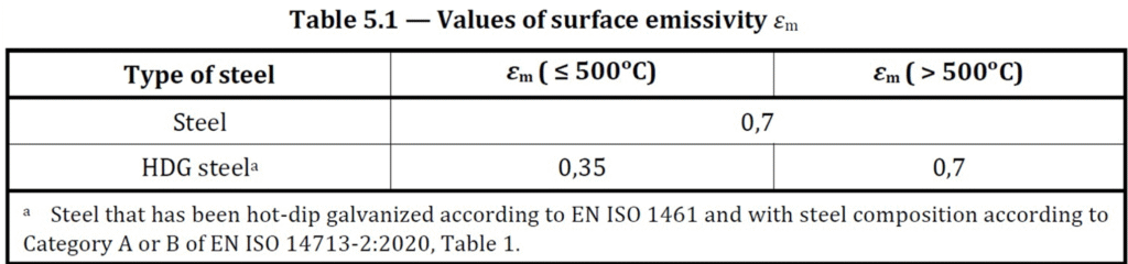
One important thing for the infleuence of the emission factor is the colour of the coating. To get a low emission factor like in the table above the coating should be bright or light grey. The zinc layer has a positive effect up to the steel reaching about 550 °C.
| Type of steel | Emission factor up to 500 C | Emission factor over 500 C |
| Carbon steel | 0,70 | 0,70 |
| Stainless steel (1) | 0,40 | 0,40 |
| HDG Steel (2) | 0,35 | 0,70 |
- According to Annex C
- Steel galvanized according to EN ISO 1461 and with steel composition according to Category A or B of EN ISO 14713-2, Table 1.
Table 1.Emission factors for black steel, stainless steel and galvanized steel.
If the coating is dark grey the emission will be higher, so it is important to use the right type of steel. According to the foot note to the table above the steel should be aluminum killed, or silicon killed with a silicon content of maximum 0.25 %. To be on the safe side it might be better to recommend a little lower maximum Si- content, depending on the construction.
| Fire resistant class | Fire resistant time (Minutes) | Symbol in the construction inspection rules |
| F 30 | ≥ 30 | Fire resistant |
| F 60 | ≥ 60 | Fire resistant |
| F 90 | ≥ 90 | Fire proof |
| F 120 | ≥ 120 | Fire proof |
| F 180 | ≥ 180 | Very fire proof |
Table 2. Fire resistance classes. Studies has shown that F30 is possible with galvanized steel without any further protection.
Interesting business case
The large business interest for fire protection with galvanizing could easily be understood from the picture below. If protection with paint is used there is demand for maintenance on a regular basis. With galvanizing no maintenance is needed and the intital costs are on the same level.
The Galvanizers Association in UK and Ireland , has with the aid of Steel Construction Institute (SCI) recently published a design guide which greatly simplifies the design of galvanized steel members in fire, avoiding any need for complex calculations. The text below describes the background.
Due to the reduction in surface emissivity of the zinc coating described in the previous section, galvanized steel members may experience a smaller temperature increase equivalent non-galvanized steel members.
The benefit of the reduced emissivity is most significant for structures that require shorter fire resistance periods, such as car parks or single storey industrial buildings, where the temperature reached by the galvanized steel members is around 500 °C. The reasons for this are:
- for temperatures lower than 500 °C, the rate at which the temperature increases in a galvanized steel member is given by a surface emissivity of 0.35, while for a non-galvanized steel member this is given by a surface emissivity of 0.70;
- steel strength is most sensitive to temperature at around 500 °C, and so in this temperature range, small differences in temperature have a pronounced effect on strength loss.
For temperatures below 400 °C, steel does not show any loss in strength. Therefore, for temperatures of around 400 °C, even though the temperature in a galvanized steel member is lower than that in an equivalent non-galvanized steel member, this does not necessarily translate into a significant difference in strength.
On the other hand, for temperatures higher than 500 °C, the surface emissivity of galvanized steel is the same as that of non-galvanized steel (0.70), and therefore, as the temperature increases, galvanized steel and non-galvanized steel temperatures converge.
Another important factor that affects the rate at which the temperature in a steel member increases is the section factor. In EN 1993-1-2, the section factor is defined as the surface area of the member exposed to a fire per unit length, Am, divided by the volume per unit length, V. Therefore, a beam exposed to a fire on four sides has a higher section factor than an equivalent one exposed on three sides.
This factor has the same effect irrespective of whether the section is galvanized or non-galvanized, as it only depends on the geometric proportions of the cross-section. That is, the larger the section factor, the faster the temperature in the member increases. As a result of this, the largest benefit of using galvanized steel over non-galvanized steel can occur in different cross-sections at different fire exposure times, depending on the section factor of the cross-section.
Figure 2 compares the rise in steel temperature of galvanized and non-galvanized steel beams for three different Universal Beam sections:
– 533 x 210 x 22
– 254 x 146 x 43
– 406 x 140 x 39
The beams are exposed to fire from three sides with section factors ksh [Am⁄V]m of 75 m-1 109 m-1 and 170 m-1, respectively. The figure indicates that for a fire exposure period of 15 minutes, the galvanized steel sections can achieve 3.5 minutes, 3.5 minutes, and 2.0 minutes longer fire resistance period compared to the equivalent non-galvanized steel sections, respectively. For a fire resistance period of 30 minutes, the galvanized steel section with a section factor of 170 m-1 (UB 254 x 146 x 43) performs very similarly to the equivalent non-galvanized steel section. This is because at 30 minutes fire exposure, the temperature in the galvanized section is 820 °C, which is significantly higher than 500 °C. For the section with a section factor of 75m-1 (UB 533 x 210 x 122), however, at 30 minutes fire exposure, there is still a noticeable gain in fire exposure time of 3 minutes.
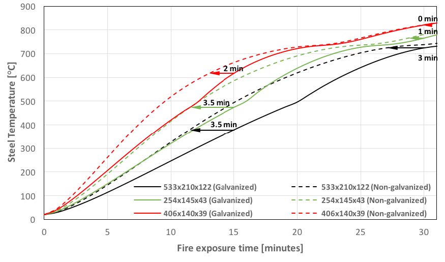
Figure 2. Temperature rise of galvanized and non-galvanized steel sections subject to the standard nominal fire curve.
If the gains in fire exposure time using galvanized steel are translated into increased resistance, the advantages are more pronounced. Figure 3 compares the resistance versus time behaviour for the galvanized and non-galvanized steel beams previously discussed.
In the figure, the resistance is represented by the maximum utilization that can be achieved by the member, calculated as the ratio of the cross-sectional resistance of the beam in the fire situation to the cross-sectional resistance at room temperature. A degree of utilization of 0.7 is indicated by a horizontal line which corresponds to the largest practical value for which a laterally restrained beam can be designed in the fire situation. This is because beams designed in fire for a degree of utilization larger than 0.7 are likely to fail at room temperature.
Bearing this in mind, at 15 minutes of fire resistance, despite the galvanized sections UB 533 x 210 x 122 (with a section factor of 75 m-1 and UB 254 x 146 x 43 (with a section factor of 109 m-1) being able to achieve a greater utilization than their non-galvanized counterparts, there is no benefit in using galvanized steel over non-galvanized steel for these sections. On the other hand, for section UB 406 x 140 x 39, which has the largest section factor (170 m-1), the maximum utilization of both galvanized and non-galvanized cross-sections is below 0.70 at 15 minutes fire exposure. In this case, using galvanized steel leads to an increase in load carrying capacity of 35% compared to using non-galvanized steel.
For sections UB 533 x 210 x 122 and UB 254 x 146 x 43, the maximum utilization that can be achieved by the non-galvanized steel sections decreases below 0.7 at noticeably shorter fire exposures than that of the galvanized sections. For example, for the steel section with the lowest section factor (UB 533 x 210 x 122), at 23 minutes fire exposure, when the maximum utilization of the galvanized section decreases to 0.70, it can carry 70 % more load than the non-galvanized section. At 30 minutes of fire exposure, even though the gain in fire resistance time is low for sections UB 533 x 210 x 122 and UB 254 x 146 x 43 (see Figure 2), they show a modest gain of 9% and 14% in load carrying capacity, respectively.
Generally speaking, a laterally restrained beam or a tension plate constructed from galvanized steel and with a section factor in the range of 105 m-1< ksh [AmV]m < 182 m-1 can carry above 30 % more load than a non-galvanized section at 15 minutes fire exposure. For laterally restrained beams, the lower bound of this section factor range depends on whether the beam is exposed to fire on three or four sides, or if it works compositely with the slab. Thus, while for beams exposed to fire on four sides the lower bound for the section factor is 105 m-1, for a beam exposed to fire on three sides, and for a composite beam this value is 145 m-1 and 115 m-1 respectively. For galvanized steel columns a similar increase in fire resistance at 15 minutes fire exposure is achieved if the section factor is in the range of 81 m-1 < ksh [Am⁄V]m < 190 m-1 For the design at 30 minutes fire exposure, an increase in fire resistance of more than 30 % can be achieved when the galvanized steel member has a section factor in the range of 33 m-1 < ksh [Am⁄V]m < 64 m-1.
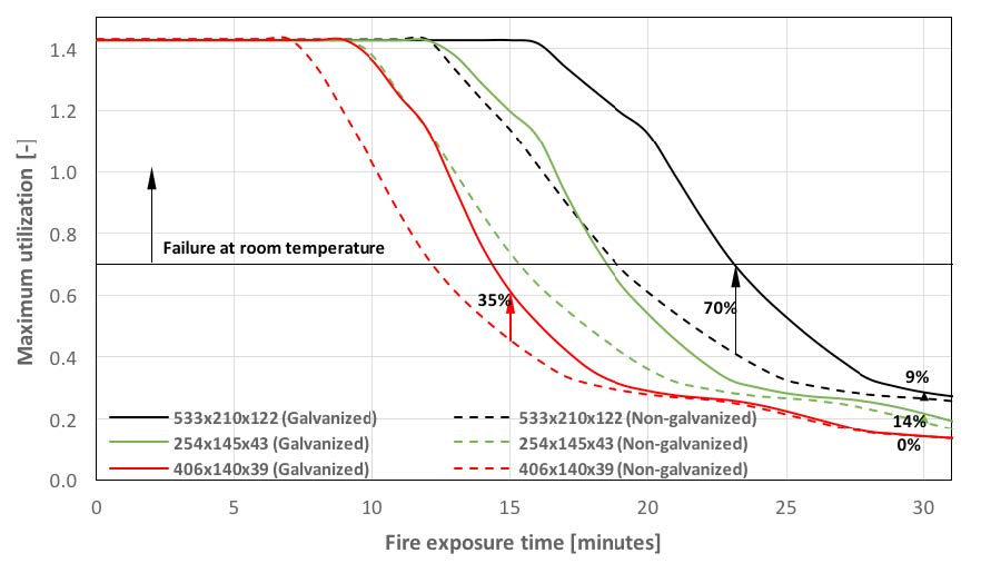
Figure 3. Maximum utilization for galvanized and non-galvanized steel beams exposed to fire on three sides.
Laboratory research – full scale testing
A number of researchers have observed that galvanized steel members reach lower temperatures during fires than equivalent non-galvanized steel members. It was postulated that this effect was due to the lower emissivity of the galvanized surface.
Emissivity values of 0.29 – 0.40 were proposed in several studies, compared to the emissivity of a non-galvanized steel surface of 0.7 which is widely used in the prediction of steel temperatures during a fire.
Although this effect has been recognized for several decades, it is only recently that sufficient weight of evidence has allowed a standardized emissivity value for galvanized steel to be determined.
According to Sala1, radiation of metal surfaces is based on atomic and molecular vibrations which depend on the chemical composition of a surface layer up to approximately 10-10 m thick. As the outer zinc layer of a galvanized surface has a thickness of 5 to 20×10-6 m, it is this layer which determines the radiation behaviour of galvanized steel.
The first tests of galvanized steel fire resistance
The first calorimeter tests to indicate the favourable influence of a galvanized coating on the temperature of steel during a fire were carried out by Heinisuo2. The specimens were subjected to a heat flow from a cone calorimeter. The derived value of emissivity of galvanized steel members below 420 °C was determined as 0.2.
The Czech Technical University in Prague validated the surface emissivity of galvanized steel in typical fire conditions by carrying out two full scale furnace tests and also testing specimens in a compartment in an experimental building 3.
Open and closed steel specimens, one metre in length, were hung from the ceiling of the compartment at the location of the highest expected gas temperature. The arrangement of the specimens ensured an even temperature distribution. Profiles were arranged in pairs (galvanized and non-galvanized). Specimens were isolated at both ends by mineral fibre wool such that the sample simulated an infinite length element and that heat transfer occurred only at the outer surface.
The temperature of each specimen was measured by one 2 mm diameter thermocouple, which was placed at the mid-point of each specimen. The gas temperature in the fire compartment was measured by twenty 3 mm thermocouples and seven plate thermocouples.
The measured temperature rise was compared against the predicted rise assuming a value for the surface emissivity of 0.32, which had been measured previously in horizontal furnace fire tests.
More recently, Gaigl4 carried out two full-scale tests and 147 laboratory tests to measure the emmisivity of galvanized steel. In small-scale laboratory tests, different types of galvanized specimens were heated and the emissivity was deduced by measuring the temperature of the specimens with thermocouples and infrared sensors.
These studies demonstrated consistent emissivity values for a range of galvanized steels with different silicon content. Silicon content is important because its presence can influence the thickness and structure of the galvanized coating. The ranges of silicon content associated with consistent emissitivity values of 0.35 were those normally encountered in modern structural steels and are defined by Category A and B of EN ISO 14713-25.
Gaigl also observed that whereas an emissitivity of 0.35 was reliably measured for temperatures up to 500 °C, at higher temperatures, changes to coating morphology will increase emissitvity to approach that of non-galvanized steel (i.e. 0.7).
Further fire tests on galvanized steel
Further supporting studies have been carried out in France. Three sets of standard fire tests were performed at Effectis, France in a joint project by CTICM, Galvazinc and EGGA . In 2016, fire tests were carried out on I and H profile steel columns exposed on four sides. In 2017, further tests were carried out on I and H profile beams exposed on three sides and I profile and hollow section columns exposed on four sides .

Specimens in CTICM- Galvazinc-EGGA tests[9] beam tests (left) and column tests in 2017 (right).
The proposed emissivity for 60 minutes fire resistance was validated through analytical prediction models at CTICM7 and in Prague8.
Implementation in Eurocode 3
Some countries in Europe have already benefited from the improved fire resistance that hot-dip galvanizing provides through national standards, and it is now also implemented in Eurocode 3. In EN 1993-1-2:2024, the lower emission value for hot-dip galvanizing steel is included, see the table below.
Summary
Studies have shown that the zinc layer has a positive effect on the heat generation during fire exposure. In many cases is it possible to withstand F30 in fire resistance of a hot-dip galvanized steel structure, without any additional fire protection. This means that the hot-dip galvanized construction can withstand 30 minutes of fire exposure according to the standard EN 13501-2 (Fire classification of construction products and building elements).
References
- SALA, A. Radiant Properties of Materials: Tables of Radiant Values for Black Body and Real Materials, PWN and Elsevier, 1986
- HEINISUO, M. Effect of zinc coating to the resistance of WQ-beam bottom flange in fire, Tampere University of Technology, 2014
- JIRKU, J. and WALD, F. Influence of Zinc Coating to a Temperature of Steel Members in Fire, Journal of Structural Fire Engineering, Vol 6, 2015
- GAIGL, C. and MENSINGER, M. Fire resistance of galvanized structures, 25th International Galvanizing Conference (Intergalva 2018), Berlin, Germany, 2018
- EN ISO 14713-2: 2020 Zinc coatings. Guidelines and recommendations for the protection against corrosion of iron and steel in structures. Hot dip galvanizing, CEN, 2020
- EN 1993-1-2: 2005 Eurocode 3: Design of steel structures – Part 1-2: General rules -Structural fire design, CEN, 2005
- BIHINA, G. Temperature assessment of galvanized steel profiles: validation of proposed emissivity values for bath galvanized steel, Technical report A 30.4.2018), Centre Technique Industriel de la Construction Métallique for the European General Galvanizers Association, 2017
- RASZKOVA, S. Emissivity of hot dip galvanized steel, MS thesis, Czech Technical University in Prague, 2019